
Understanding Serial Ports: Lamp Control via Web App and Serial Communication

With over a decade of hands-on experience, I specialize in building robust web applications and scalable software solutions. My expertise spans across cutting-edge frameworks and technologies, including Node.js, React, Angular, Vue.js, and Laravel. I also delve into hardware integration with ESP32 and Arduino, creating IoT solutions.
Are you interested in connecting Arduino boards (or other microcontrollers) to the web to create interactive projects? If so, this project is for you! We'll guide you through the process of building a web-controlled lamp, showcasing the power of serial communication and laying the foundation for further exploration.
Unleashing the Power of Serial Ports:
Imagine a bridge connecting the digital realm of your computer to the tangible world of sensors and actuators. That's what a serial port does, allowing data to flow bi-directionally, one bit at a time. This project hinges on this simple yet powerful technology.
Hardware and Software:
Arduino Board: Any Arduino board with a USB port will do.
RGB LED: A common component to add color to your project.
Jumper Wires: Connect various components.
Breadboard: Simplifies prototyping and wiring.
Node.js and npm: Used for creating the web server.
Serial Port Monitor (optional): For initial testing and debugging.
Building the Lamp Circuit:
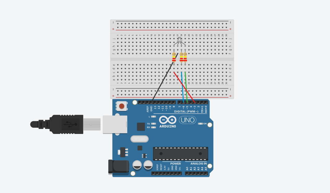
Before the code comes to life, we need to assemble the hardware. Gather your Arduino board, an RGB LED, resistors, and some jumper wires. Connect the components as shown in the diagram, powering the LED from the Arduino and controlling its individual red, green, and blue channels with separate pins. (red to Pin 3, green to Pin 5, and blue to Pin 6)
Crafting the Code Symphony:
Now, let's orchestrate the communication between our devices. The Arduino code listens for incoming data through the serial port, parses it as color information, and then uses that information to adjust the LED's brightness accordingly. The Node.js server acts as the middleman, receiving color selections from the web app and relaying them to the Arduino. Finally, the React.js frontend provides a user-friendly interface where you can choose your desired lamp color.
Delving into the Code Details:
Arduino Code:
const byte PIN_LED_R = 3;
const byte PIN_LED_G = 5;
const byte PIN_LED_B = 6;

const byte dt = 1000;
void setup() {
  Serial.begin(9600);

  pinMode(PIN_LED_R, OUTPUT);
  pinMode(PIN_LED_G, OUTPUT);
  pinMode(PIN_LED_B, OUTPUT);
}

void loop() {

  // Check if there is serial data available
  if (Serial.available() > 0) {
    // Read the incoming data
    String data = Serial.readStringUntil('\\n');
    Serial.println(data);
    Serial.print("Getting Color : ");
    Serial.println(data);
    // Parse the data and extract RGB values
    parseAndDisplayColor(data);
  }

  delay(dt);
}

void displayColor(byte r, byte g, byte b) {
  analogWrite(PIN_LED_R, r);
  analogWrite(PIN_LED_G, g);
  analogWrite(PIN_LED_B, b);
}

void parseAndDisplayColor(String data) {
  if (data.length() == 7 && data[0] == '#') {
    // Extract hexadecimal values for R, G, and B
    long hexValue = strtol(data.substring(1).c_str(), NULL, 16);

    int r = (hexValue >> 16) & 0xFF;
    int g = (hexValue >> 8) & 0xFF;
    int b = hexValue & 0xFF;

    // Display the color
    displayColor(r, g, b);
  }
}
Let's break down the void loop() part of the Arduino code:
Serial Data Reception
if (Serial.available() > 0) { ...}This line checks if there is any data available to be read from the serial port. If there is, it proceeds to read the incoming data.Reading:
Serial.readStringUntil('\\n'): Reads the incoming data until it encounters a newline character ('\\n'). This assumes that the data is sent in lines.
Parsing and Displaying Color:
Calls the function
parseAndDisplayColor(data)to parse the received color data and display it on the RGB LED.
Now, let's take a look at the helper functions:
void displayColor(byte r, byte g, byte b) {
  analogWrite(PIN_LED_R, r);
  analogWrite(PIN_LED_G, g);
  analogWrite(PIN_LED_B, b);
}

void parseAndDisplayColor(String data) {
  if (data.length() == 7 && data[0] == '#') {
    // Extract hexadecimal values for R, G, and B
    long hexValue = strtol(data.substring(1).c_str(), NULL, 16);

    int r = (hexValue >> 16) & 0xFF;
    int g = (hexValue >> 8) & 0xFF;
    int b = hexValue & 0xFF;

    // Display the color
    displayColor(r, g, b);
  }
}
displayColor Function:
analogWrite(PIN_LED_R, r);: Sets the intensity of the red LED based on the value ofr. Similar statements apply to the green and blue LEDs.
parseAndDisplayColor Function:
Check if the received data has a length of 7 characters and starts with the '#' character, ensuring it is a valid color representation.
Extracts the hexadecimal value from the color data (excluding the '#').
Separates the hexadecimal value into individual R, G, and B components.
In summary, the void loop() continuously checks for incoming serial data, reads and prints the data, then parses and displays the color on the RGB LED based on the received information. The delay between iterations helps control the loop's execution speed.
Node.js Server Code:
const express = require("express");
const { SerialPort } = require("serialport");
const { ReadlineParser } = require("@serialport/parser-readline");
const cors = require("cors");

const app = express();
const port = 3001;
const portName = "COM3"; // Change 'COM3' to your Arduino port
const portNumber = 9600;
const arduinoPort = new SerialPort({ path: portName, baudRate: portNumber });
const parser = arduinoPort.pipe(new ReadlineParser({ delimiter: "\\r\\n" }));

app.use(express.json());
app.use(cors());

app.post("/sendData", (req, res) => {
  const { data } = req.body;
  console.log(`Sending data to Arduino: ${data}`);

  arduinoPort.write(data);
  res.send("Data sent to Arduino");
});

app.listen(port, () => {
  console.log(`Server is running on <http://localhost>:${port}`);
});
const arduinoPort = new SerialPort({ path: portName, baudRate: portNumber });
The SerialPort class from the serialport library is used to create an instance called arduinoPort. This instance represents the communication channel between the Node.js server and the connected Arduino. The parameters passed to the SerialPort constructor include the path to the Arduino's serial port (portName) and the baud rate (portNumber).
const parser = arduinoPort.pipe(new ReadlineParser({ delimiter: "\\r\\n" }));
The ReadlineParser is created and attached to the arduinoPort. This parser is essential for handling the incoming data as lines, which is crucial when dealing with data sent over serial communication. The delimiter option specifies the line ending character(s) that indicate the end of a message.
API Endpoint for Sending Data:
  app.post("/sendData", (req, res) => {
    const { data } = req.body;
    console.log(`Sending data to Arduino: ${data}`);

    arduinoPort.write(data);
    res.send("Data sent to Arduino");
  });
This endpoint (
/sendData) is a route that listens for incoming POST requests. When the server receives a request, it extracts thedatafrom the request body, logs the information, and writes the data to the Arduino through thearduinoPortinstance using thewritemethod.Finally, it sends a response indicating that the data has been successfully sent.
React.js Frontend Code:
import { useState } from "react";
import "./App.css";
import Lamp from "./Lamp";
import axios from "axios";

function App() {
  const [lampColor, setLampColor] = useState("#f1c40f");

  const handleColorChange = (e) => {
    setLampColor(e.target.value);
    sendDataToArduino();
  };

  const sendDataToArduino = () => {
    axios
      .post("<http://localhost:3001/sendData>", { data: lampColor + "\\n" })
      .then((response) => {
        console.log(response.data);
      })
      .catch((error) => {
        console.error("Error sending data to Arduino:", error);
      });
  };

  return (
    <div className="flex h-screen items-center justify-center">
      <Lamp color={lampColor} />

      <div className="ml-4">
        <label htmlFor="colorInput" className="text-gray-700">
          Lamp Color:
        </label>
        <input
          type="color"
          id="colorInput"
          value={lampColor}
          onChange={handleColorChange}
          className="ml-2"
        />
      </div>
    </div>
  );
}

export default App;
A color picker allows users to select colors.
handleColorChange()updates the selected color and triggers data transmission.axios.post()sends color data to the Node.js server.
Dive into the Project Code:
This project code is available on GitHub: serialport-communication The repository contains all the necessary files and a detailed readme explaining the setup, code, and usage instructions. Feel free to explore and customize the code further based on your preferences.
Key Components Explained:
Serial Communication: This project hinges on serial communication, a method of transmitting data one bit at a time. It acts as the bridge between your computer and the Arduino, enabling control over the lamp.
Libraries and Frameworks: The code leverages powerful libraries and frameworks to simplify development.
Serialport: This library handles efficient serial communication between the Node.js server and the Arduino board.
Express: This framework facilitates the creation and management of the web server, allowing you to interact with the lamp through your web browser.
React.js: This popular JavaScript library empowers the creation of a user-friendly interface for selecting and controlling the lamp's color.
Data Parsing: The Node.js server plays a crucial role in parsing the incoming color data from the web app. It extracts the relevant information and transmits it to the Arduino in a compatible format.
User Interaction: The React.js frontend provides a seamless user experience. You can choose your desired lamp color using a convenient color picker, and the changes are instantly reflected in the real world.
Beyond the Basics:
This project serves as a springboard for your journey into the exciting world of interactive electronics. Feel free to experiment and expand upon this foundation:
Sensory Integration: Incorporate sensors to gather environmental data (e.g., temperature, light levels) and adjust the lamp color accordingly, creating an interactive and responsive environment.
Multi-LED Control: Connect and control multiple LEDs to create dynamic lighting effects, transforming your space with vibrant colors and animations.
Don't hesitate to explore and build upon this project! With your imagination and ingenuity, you can unlock endless possibilities in the realm of interactive electronics. So, grab your Arduino, delve into the code, and start creating!
Remember: The GitHub repository mentioned above holds all the essential resources to get you started. Embrace the learning process, experiment, and have fun!